


an instrument to gauge beat on medicinal grounds.
Keywords: Microcontroller, beat, sensors, IR, IC, medicinal
I. INTRODUCTION
In medical science, Pulse is characterized as the standard beating of the heart, particularly when it is felt at the wrist or side of the neck. Heart rate is the quantity of heartbeats per unit time. An IR pair is utilized to gauge this heartbeat through the veins of a finger. The utilization of IR to sense heart rate was concentrated on from before biomedical checking frameworks. The microcontroller based inserted framework has been made to be effective and precise. Hence, Intel 8051 utilized as a part of this framework completed the choice making procedures by utilizing the info simple signs to count and procedure the estimation of heart beat every moment in the 7-segment display. Three 7- segment display have been incorporated in the yield module of the framework.
A beating heart increases the concentration of red blood cells each time it pumps. This change in concentration is detected and an average count is maintained. A low cost microcontroller makes the system simple and yet accurate to count the heart beat
II. RELATED WORK
This framework takes thoughts from others which have been systemised before. It is an augmentation to a sensor framework that has been given before . Anyway, here the framework is making utilization of a minimal effort microcontroller 8051 which makes the programming simple and chops down the expense per gadget. The precision of the framework is additionally high as outer precious stone
gives the premise of clock number. This check is essential for the augmentation counter that has been made to be utilized as a part of the program.
III. SYSTEM DESIGN DESCRIPTION
The whole system has been designed to be used with a 9 V DC supply. The Complete system has been divided into
three different parts. These are:
A The Input Module
B The Microcontroller Unit
C The Output Display Unit
A. The Input Module:
This consists of amplification circuits and IR pair. The two major components of this module are :


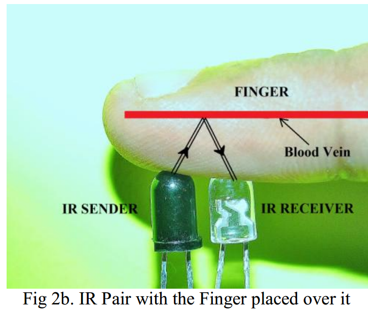
where the white LED is Sender and Blue Led is Receiver . when sender on it pass infrared rays on finger when we placed on it. and Receiver count the blood cells. that tells us about heartbeat rate.
LM 324 : It is a Dual-in-Line Packaged Quad processor which consists of four independent, high gain,internally frequency compensated operational amplifiers which are specifically designed to operate on single power supply over a wide voltage range. Three of them have been used to amplify the signals from the IR. Figure (b) is the internal circuit diagram of the IC.
IR PAIR : An IR transmitter and receiver pair is used. Here the transmitter transmits the signal through thefinger which is placed over it. Whenever there is an increase in concentration of red blood cells in the vein,the signals detect by bouncing back to the receiver IR. This way each time the blood is pumped throughoutthe body, a localised area of the human body will help to detect it. This signal is then send to the microcontroller unit. Figure (b) describes the working of the IR pair.
B. The Micrcontroller Unit:
An Intel 8051 microcontroller is utilized as the fundamental choice making processor in the framework. It is an ease, Harvard structural planning, CISC guideline set single chip Microcontroller . Its building design incorporates CPU, RAM, ROM, I/O, Interfere with rationale, clock, and so on in a solitary processor. It has a 8 bit collector and 8 bit ALU in this way making it a 8 bit processor. This unit likewise utilizes a gem to produce clock recurrence. This precious stone has been particularly decided to have 11.0593MHz of recurrence and the clock and deferral projects have been created mulling over this.
C. The Output Display Unit:
This module consist of three distinctive 7-fragment show units. They are all normal anode sort which has been joined serially.A 7 portion showcase or a 7-fragment pointer is a type of electrical gadget comprising of seven light radiating diodes organized in a way to show Arabic numerical. The gleaming of each of these diodes can be controlled by the data which is by and large given to it by a microcontroller [8]. The exchanging instrument of these parts have been joined and controlled by the microcontroller. The source is utilized utilizing a BJT and is then autonomously joined with each of the showcase units. The 2N2222 is a NPN sort transistor utilized alongside the 7 section show IC. It lives up to expectations at high velocity with low to medium measures of force. This is fundamentally utilized as an exchanging gadget that does not permit direct stream of voltage between microcontroller port and the showcase units.
IV. IMPLEMENTATION
The complete circuit diagram is shown in figure 3.

For a normal person, the blood flows through the veins 72 times per minute. The input IR pair senses this and each time this is sensed a signal is given to the microcontroller which counts the signals received. A potentiometer has been used to calibrate the intensity and the efficiency of the IR in natural conditions. The microcontroller then sends this logical count to the display units which give then count of heart rate.The Microcontroller programming has been firstly implemented in Kiel µvision 4. After the required debugging the hex codes have been transferred to a chip burner which assigns the assembly language program into the Intel 8051 used in the physical device. A window showing the program simulation and implementation is given in figure 4.The microcontroller program has been developed to check the analog input that is received from the amplifier circuits. This signal is taken into the processor through port P3.5. Ports P1.0, P1.1 and P1.2 are used to turn ON and OFF each of the &-segment display independently. The output is defined by the ports P0.0 to P0.7 which are connected from a to h of the 7-segment display respectively. Binary codes of three digits are used by each of the ports to define each of the diodes of the display units. For example if port 0.0 has the value 010, then the second display unit D2 willhave its „a‟ diode switched ON [9]. This serially switches ON or OFF the respective diodes in the 7-segment display so as to show the correct value the output that has been calculated.

For a normal person, the blood flows through the veins 72 times per minute. The input IR pair senses this and each time this is sensed a signal is given to the microcontroller which counts the signals received. A potentiometer has been used to calibrate the intensity and the efficiency of the IR in natural conditions. The microcontroller then sends this logical count to the display units which give then count of heart rate.The Microcontroller programming has been firstly implemented in Kiel µvision 4. After the required debugging the hex codes have been transferred to a chip burner which assigns the assembly language program into the Intel 8051 used in the physical device. A window showing the program simulation and implementation is given in figure 4.The microcontroller program has been developed to check the analog input that is received from the amplifier circuits. This signal is taken into the processor through port P3.5. Ports P1.0, P1.1 and P1.2 are used to turn ON and OFF each of the &-segment display independently. The output is defined by the ports P0.0 to P0.7 which are connected from a to h of the 7-segment display respectively. Binary codes of three digits are used by each of the ports to define each of the diodes of the display units. For example if port 0.0 has the value 010, then the second display unit D2 willhave its „a‟ diode switched ON [9]. This serially switches ON or OFF the respective diodes in the 7-segment display so as to show the correct value the output that has been calculated.


V. RESULTS
The result of this system is the output count which the microcontroller displays on the 7-segment display. An ideal graph showing the voltage vs time curve of a beating heart is shown in figure 6. In this a threshold has been defined which verifies the amount of voltage over which the IR senses obstacle and the microcontroller increments its count by one.

VI. CONCLUSION
Assembly Language Code:
ORG 000H // origin
MOV DPTR,#LUT // moves starting address of LUT to DPTR
MOV P1,#00000000B // sets P1 as output port
MOV P0,#00000000B // sets P0 as output port
MAIN: MOV R6,#230D // loads register R6 with 230D
SETB P3.5 // sets P3.5 as input port
MOV TMOD,#01100001B // Sets Timer1 as Mode2 counter & Timer0 as
Mode1 timer
MOV TL1,#00000000B // loads TL1 with initial value
MOV TH1,#00000000B // loads TH1 with initial value
SETB TR1 // starts timer(counter) 1
BACK: MOV TH0,#00000000B // loads initial value to TH0
MOV TL0,#00000000B // loads initial value to TL0
SETB TR0 // starts timer 0
HERE: JNB TF0,HERE // checks for Timer 0 roll over
CLR TR0 // stops Timer0
CLR TF0 // clears Timer Flag 0
DJNZ R6,BACK
CLR TR1 // stops Timer(counter)1
CLR TF0 // clears Timer Flag 0
CLR TF1 // clears Timer Flag 1
ACALL DLOOP // Calls subroutine DLOOP for displaying the count
SJMP MAIN // jumps back to the main loop
DLOOP: MOV R5,#252D
BACK1: MOV A,TL1 // loads the current count to the accumulator
MOV B,#4D // loads register B with 4D
MUL AB // Multiplies the TL1 count with 4
MOV B,#100D // loads register B with 100D
DIV AB // isolates first digit of the count
SETB P1.0 // display driver transistor Q1 ON
ACALL DISPLAY // converts 1st digit to 7seg pattern
MOV P0,A // puts the pattern to port 0
ACALL DELAY
ACALL DELAY
MOV A,B
MOV B,#10D
DIV AB // isolates the second digit of the count
CLR P1.0 // display driver transistor Q1 OFFSETB P1.1 // display driver transistor Q2 ON
ACALL DISPLAY // converts the 2nd digit to 7seg pattern
MOV P0,A
ACALL DELAY
ACALL DELAY
MOV A,B // moves the last digit of the count to accumulator
CLR P1.1 // display driver transistor Q2 OFF
SETB P1.2 // display driver transistor Q3 ON
ACALL DISPLAY // converts 3rd digit to 7seg pattern
MOV P0,A // puts the pattern to port 0
ACALL DELAY // calls 1ms delay
ACALL DELAY
CLR P1.2
DJNZ R5,BACK1 // repeats the subroutine DLOOP 100 times
MOV P0,#11111111B
RET
DELAY: MOV R7,#250D // 1ms delay
DEL1: DJNZ R7,DEL1
RET
DISPLAY: MOVC A,@A+DPTR // gets 7seg digit drive pattern for current value in A
CPL A
RET
LUT: DB 3FH // LUT starts here
DB 06H
DB 5BH
DB 4FH
DB 66H
DB 6DH
DB 7DH
DB 07H
DB 7FH
DB 6FH
END // End of the program
Refrence:
Muhammad zeeshan rasool
BS(Electrical Engineering)
if any question about this project please pass comments.
0 comments:
Post a Comment